Behringer SHARK DSP110 Operations Instructions
Browse online or download Operations Instructions for Processors Behringer SHARK DSP110. Behringer SHARK DSP110 Operating instructions User Manual
- Page / 26
- Table of contents
- BOOKMARKS
- DSP110 1
- 1. INTRODUCTION 3
- 1.2 Before you begin 4
- 1.3 Control elements 6
- SHARK DSP110 10
- 2. APPLICATIONS 11
- 2.3 The integrated Delay 18
- 2.4 The Noise Gate function 18
- 2.6 The Compressor function 19
- 3. INSTALLATION 20
- 4. SPECIFICATIONS 22
- 5. RACKMOUNT (OPTIONAL) 23
- 6. WARRANTY 25
- FEDERAL COMMUNICATIONS 26
- COMMISSION COMPLIANCE 26
- INFORMATION 26
Summary of Contents
SHARK® DSP110Userss ManualVersion 1.2 April 2001www.behringer.comENGLISHDATA-MANFULL_DSP110_ENG_Rev. E.p65 20.04.01, 15:451
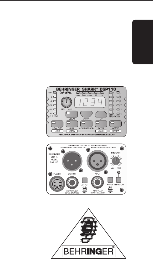
10SHARK DSP110Fig 1.3: Rear panel control elements and connectors of the DSP11014This is the SHARKs balanced XLR output.15This is the SHARKs balance
11SHARK DSP11020This is the SHARKs balanced JACK input, which is wired in parallel to the XLRinput.21Use the INPUT LEVEL switch to select the input s
12SHARK DSP110Fig. 2.1: The SHARK connected between microphone and microphone input onconsole2.1.2 Connection between line-level source and mixing con
13SHARK DSP1102.1.3 Connection between mixing console and power amplifierWhen you use the SHARK as a Delay Line unit for speaker systems placed at var
14SHARK DSP1102.1.4 The SHARK used in the monitor pathInserting the DSP110 in the monitor path of your mixing console gives you utmostprote
15SHARK DSP110Fig. 2.4: Two SHARKs in the monitor path2.1.5 The SHARK used in single channels and subgroupsWhenever you want to make sure that wanted
16SHARK DSP110Fig. 2.5: The SHARK in the insert path2.1.6 Automatic tuning in of P.A. and monitor systemsWith the DSP110 you can improve the
17SHARK DSP1102.2 The Feedback Destroyer in the SHARKThe SHARK identifies feedback by splitting the entire frequency spectrum (20 Hz to20 kHz) into se
18SHARK DSP1102.3 The integrated DelayIn addition to speakers on or near the stage, major-scale installations often havespeaker groups p
19SHARK DSP110between microphones, without producing any unpleasant side effects.A typical Gate application is the processing of vocal tracks.
2SHARK DSP110This symbol, wherever it appears,alerts you to the presence ofuninsulated dangerous voltage insidethe enclosure - voltage that
20SHARK DSP110from 90 dB to 50 dB or less, which ensures the troublefree further processing ofsignals, e.g. in broadcast, stage or
21SHARK DSP110Unbalanced use ofmono 1/4" jack plugsRingBalanced use ofstereo 1/4" jack plugsBalanced use with XLR connectors1 232 13InputOut
22SHARK DSP1104. SPECIFICATIONSAUDIO INPUTSConnectors XLR and 1/4" jackType RF filtered, servo-balanced inputImpedance 6 kOhms balanced, 3 kOhms
23SHARK DSP1105. RACKMOUNT (OPTIONAL)With the available rackmount (optional) you have the possibility to place five SHARKson two units of space in you
24SHARK DSP110Fig. 5.1: Installation of the DSP110 on the available rackmount (optional)+ Please, only use the supplied screws to install the
25SHARK DSP1106. WARRANTY6. WARRANTY§ 1 WARRANTY CARD/ONLINE REGISTRATIONTo be protected by the extended warranty, the buyer must completeand re
FEDERAL COMMUNICATIONS COMMISSION COMPLIANCE INFORMATIONResponsible party name: MUSIC Group Services USA, Inc.Address: 18912 North Creek Parkway,Sui
3SHARK DSP1101. INTRODUCTIONThank you very much for expressing your confidence in BEHRINGER products bypurchasing the SHARK DSP110.+ This m
4SHARK DSP110Fig. 1.1: Typical feedback loop1.2 Before you beginYour SHARK was carefully packed in the factory and the packaging is designed topr
5SHARK DSP110Be sure that there is enough air space around the unit for cooling and please do notplace the SHARK on high-temperature devices suc
6SHARK DSP1101.3 Control elementsFig. 1.2: Front panel control elements of the DSP1101The CLIP LEVEL METER shows you whether or not the dig
7SHARK DSP1104The 4-digit DISPLAY reads the absolute values of the adjusted parameters.5The FB-D FILTER STATUS LEDs display the status of each of th
8SHARK DSP1109The LOW CUT button lets you enter the high pass filters cut-off frequency(20 to 150 Hz). When set to OFF the filter is inop
9SHARK DSP110+ When both FILTER LED and display stop flashing, the FILTER LEARN functionhas been completed. Press the FILTER key to cancel the functio
Related products and manuals for Processors Behringer SHARK DSP110
 (34 pages)
(9 pages)
(34 pages)
(9 pages)
 (10 pages)
© 2020, manymanuals.com. All rights reserved. | 0.058 s |
 Manymanuals.com
 Manymanuals.de
 Manymanuals.fr
 Manymanuals.it
 Manymanuals.pl
 Manymanuals.cz
 Manymanuals.es
 Manymanuals-pt.com
Comments to this Manuals